In SoC, more and more Logic Gate is required according to Moore’s law, and accordingly, the power consumption also increases. The heat generated in highly integrated circuits resulted in the rise of the consideration element of operating temperature compared to the existing designed circuits. When the operating temperature is shaken, Vth changes according to the body effect, which may result in performance degradation. Therefore, when the temperature rises with the sensor that measures the temperature, the need for a feedback circuit that adjusts the body Bias has begun to emerge. The Adaptive Body Bias Generator (hereinafter referred to as ABBG) can be said to be a block that plays a role in adjusting the body Bias of each transistor more quickly and accurately according to the sensed temperature.
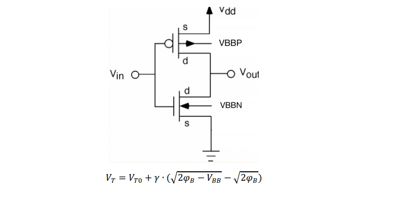
Let’s go first about Body Bias. It can be seen that the threshold voltage changes according to the body Bias as shown in the following equation.
Here, if the body of NMOS is increased and the body of PMOS is lowered, Vt is lowered, and both Speed and Leakage are increased. This is called forward body biasing. Conversely, lowering the NMOS body and increasing the PMOS body increases the Vt, and both speed and leakage decrease. This is called reverse baby biasing. By appropriately adjusting the body bias level in this way, speed and current can be adjusted, and PVT variation can be adjusted through this. Depending on the process, sample dies in the slow region (SS) can reduce dispersion by the process by applying forward bias for Speed enhancement and sample dies in the leaky region (FF) by applying Reverse Bias for Leakage Current suppression.
In order to perform this ABBG function, it is necessary to monitor whether the transistor is in the Leakage region or the Slow Region, and designing such a monitoring circuit is the core of the ABBG Block. As shown in the following figure, ABBG consists of REF, Error amp, and Push-pull Amplifier. This project was conducted in the form of a thesis study and simulation analysis on the Push-pull Class-AB Output amplifier required for this ABBG.
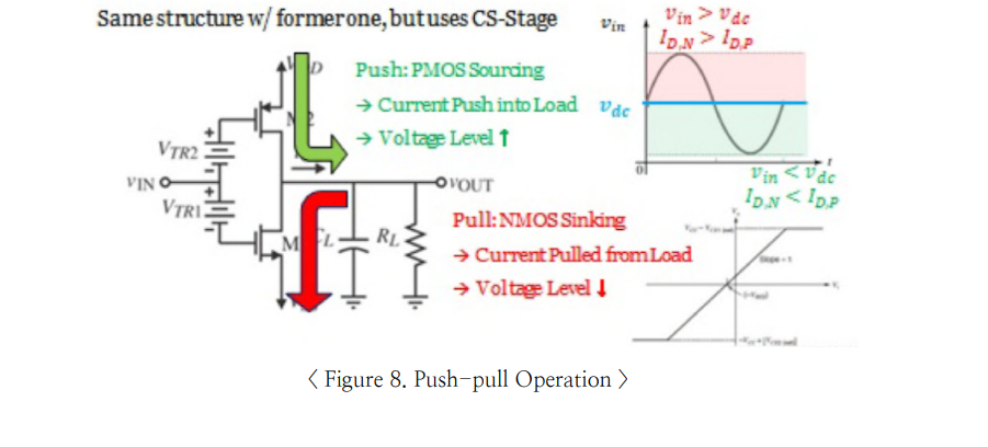
The most important performance factors in ABBG Output Stage are Swing, Linearity, and Power Consumption. First, it must be able to cover the entire rail-to-rail voltage, and it must show a linear response without a dead zone in the middle. Also, if you always need to drive Current, such as Source Follower, you should avoid it because of the significant power consumption. Therefore, it is necessary to use Class-AB Push-pull Amp with Diode bias added instead of the basic Source Follower (Class-A) or Class-B Output Stage where Deadzone occurs. In Figure 8 below, Push-pull Operation is summarized.

Simulation results are difficult to attach due to in-house security, but due to PMOS/NMOS Sink/Source Coverage Limit and Settingling, we cannot ideally cover the swing, but it can be found that it can cover with quite excellent performance of about 60 dB.
