Note: Source code details have been omitted for security reasons.
Overview of LoRa
LoRa (Long Range) is a proprietary wireless communication technology that is used for long-range communication and low-power, low-data-rate applications. LoRa is based on the spread spectrum technique and uses a frequency-hopping spread spectrum (FHSS) approach to transmit data over long distances.
LoRa Modulation
-
Employs CSS(Chirp Spread Spectrum modulation)
Chirp: Signals with constantly increasing(Up-) or decreasing(Down-) frequency
Usually up-chirp utilized on LoRa Mod -
Key parameter: Spreading Factor (SF)
SF(Spreading Factor): Bits per symbol (5<SF<13)
The SF satisfies SF = B · T , where B is bandwidth and T is chirp period. There are at most SF cyclically shifted up-chirp symbols given a specific SF. An up-chirp can be represented as the following formula:
The higher the SF, the longer the time on air, resulting in higher energy per bit.
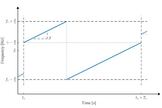
A LoRa symbol is a cyclic shift in frequency that is controlled by chirping rates represented with a spreading factor (SF), which determines the symbol’s spreading over time. A normalized up-chirp LoRa signal is expressed as follows:
The frequency offset, γ(m), and chirp slope, β, are obtained from m, the symbol being modulated, B, the transmission bandwidth, and Ts, the symbol time. The SF has a range of SF ∈ {6, 7, 8, 9, 10, 11, 12}, while the bandwidth B ∈ {125, 250, 500} kHz. The chirp rate has a slope of fhigh − flow = B/Ts.
An example of a LoRa chirp is shown in the above figure, which depicts the spectrogram of a LoRa symbol, highlighting the cyclic frequency shift. Each symbol represents M = 2^SF bits according to the LoRa modulation convention.
With these knowledges, we can make chirp generator program for given domain as follows:
LoRa Waveform Structure
- Preamble -> (Sync) -> SFD -> (Header) -> Data
Preamble: Sync detection, i.e., Start point of the signal
Sync: Frame sync, utilized after demodulation - bit analysis
SFD(Start Frame Delimiter): Identifier, i.e., Delimiter, Down-chirp
Data: CSS-Modulated data, varying start frequency
LoRa Demodulation
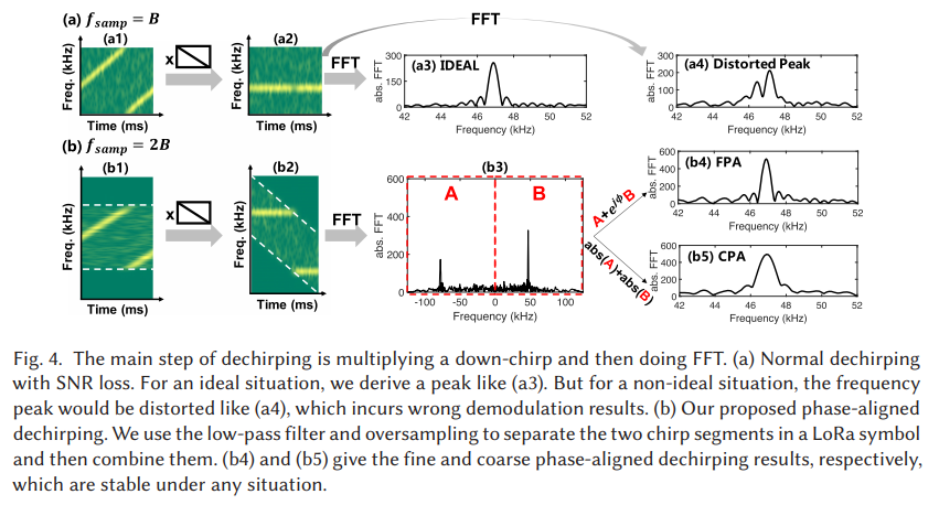
Typically, LoRa detection is achieved in two steps: (i) first, the signal is de-chirped, then (ii) typical FSK demodulation is applied. De-chirping is achieved by mixing the received LoRa symbol with an inverted chirp (down-chirp) with no frequency offset. Since the demodulator has no prior knowledge of the transmit symbols, the de-chirping signal utilizes γ(0) = −B/2. Hence, the resulting signal is given as follows:
which is a typical M-ary FSK signal. Each symbol is now represented with a frequency shift of mδf, where δf is the bandwidth divided by the number of steps. In LoRa, it happens that this value is equivalent to the symbol rate as follows, δf = 1/T.
Now that the symbol is modulated using FSK, we can use conventional FSK demodulation methods to detect the symbol. Here, we utilized Non-coherent detection, attained by using energy detection in the frequency domain, where the maximum PSD peak location indicates the extracted symbol, formulated as follows:
where R(f) is implemented as the fast Fourier transform (FFT) of the FSK signal, R(f) = FFT{r(t)}.
Using this approach, we can easily implement a LoRaWan-like demodulator by following these simple snippet.
To de-chirp the signal, we start by cross-correlating it with a reference downchirp. This is done using np.convolve with mode 'valid'. The index where the maximum correlation is achieved corresponds to the timing of the received data, which we obtain using data_index = argmax(crosscorr_result). We then perform an FFT on each dechirped data and proceed with symbol-to-bit mapping as described earlier. Using multiprocessing, as discussed in earlier post, can accelerate the iterative loop.
LoRa Decoding
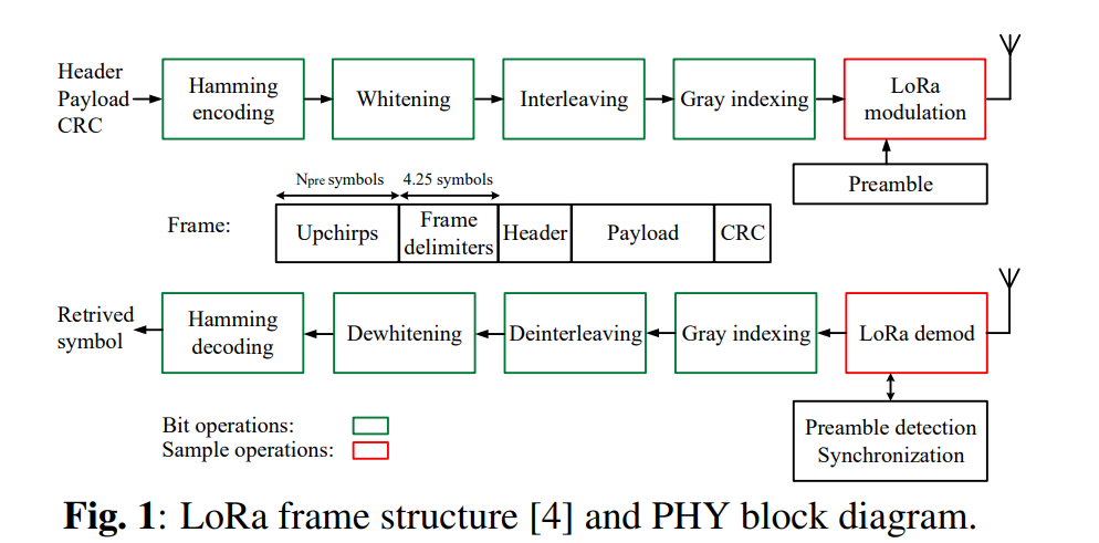
The LoRa receiver performs synchronization, frequency-offset estimation, and compensation prior to demodulation. Gray coding, de-interleaving, de-whitening, and Hamming decoding are carried out to recover the information as described in the figure above. In this post, we will discuss the concept of those decoding processes in general and how they apply to the LoRa decoding process.
Gray coding
A gray coding is a mapping between a symbol in any numeric representation to a binary sequence. The particularity of the obtained binary sequence is that adjacent symbols in the original representation only differ by one bit in the gray representation. This property of a gray codes make them very useful in many wireless communication modulations where it is more likely to misinterpret a symbol by an adjacent one than another random one. It is noteworthy that in the case of CSS modulation it is not the white noise that causes this misinterpretation between adjacent symbols but the carrier and sampling frequency offset. In the case of LoRa, the symbols can be seen as integers between 0 and 2^SF − 1 and by making usage of gray coding to map them to binary strings, we increase the performance of the forward error correction mechanisms capable of correcting one erroneous bit in a codeword.
Unfortunately, it is possible to create different binary string sequences respecting the conditions to be considered as a gray code. Furthermore it is just a mapping between decimal numbers and binary string, meaning that once we have found a sequence of 2^SF binary string differing by only one bit, we can still define any of them to by mapped to 0. Finally the direction of mapping of the following symbol can also be chosen freely. This leads to 2 ∗ 2^SF possibilities for every possible gray sequence. The method used in was a brute force approach, which found out that the method of the figure 2.4 is used.
Important Note: The standard gray code being used is given by Cn = Bn XOR (Bn » 1) where Bn is the left MSB binary representation of n. On top of the mapping using this gray code, a shift of -1 is used, i.e., v = (v0 − 1) XOR ((v0 − 1) » 1).
-
In MATLAB
Read the following document to understand the bin2gray function.
-
In Python
We can note that the gray coding doesn’t occur in the conventional order but in reverse which still holds the property that one adjacent symbol mistake leads only to one bit being wrong. The figure 2.5 present the binary values obtained after gray encoding of the received LoRa symbols line by line. The white and black square are respectively ones and zeros.
Interleaving and De-interleaving
Interleaving is a technique used to improve the performance of error correction codes by breaking the correlation between errors caused by noise or fading. It works by spreading the bits of a codeword across multiple symbols, so that if a symbol is corrupted, the errors will be distributed across multiple codewords rather than concentrated in one. This increases the effectiveness of the error correction code, but also increases the latency of the communication. Interleaving can also be used to improve the robustness of data transmitted over a noisy channel.
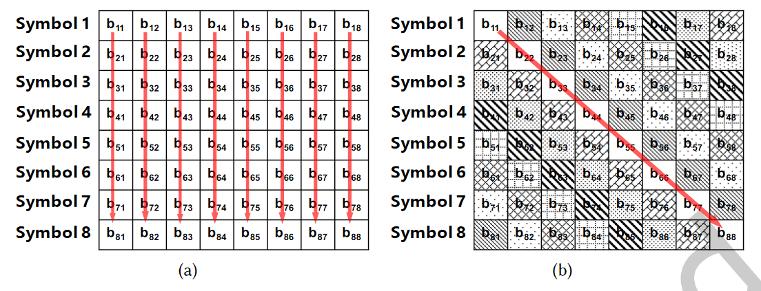
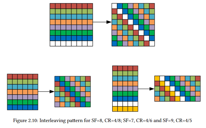
For instance, LoRa signal applies diagonal interleaving instead of conventional row-line interleaving. The Figure (a) shows the column-major order row-line interleaving of eight symbols. For row-line interleaving, the LSBs (bi,1) of the eight symbols are assembled into a byte. From Section 3 we know that the LSBs of a symbol are more fragile than the most signiicant bits (MSBs) of the symbol. From the perspective of FEC, it is a bad design to group fragile bits together. Figure 9(b) shows diagonal interleaving used in LoRa. Diagonal interleaving distributes the fragile LSBs into diferent bytes and is more robust. We then manipulate the transmitted packets to derive the detailed diagonal mapping.
As an example, we send packets with SF = 8 and CR = 4/8 in implicit header mode. Thus, the interleaving block is an 8 × 8 block as shown in Figure 9(b). First, we assume the FEC used in CR = 4/8 is the standard (7,4) Hamming code with one bit extension. Therefore, after Gray coding and Whitening, the codeword for nibble 0000 is 00000000, and the codeword for 1111 is 11111111. Suppose the sending bytes are all zeros except that the fourth byte is 0x0F, we observe b11 = b22 = · · · = b88 = 1 in Figure 9(b). Therefore the main diagonal represents the fourth byte 0x0F. The one bin shift problem mentioned in Gray coding relects here that we cannot always get eight ones in a block if we directly apply the standard Gray coding. Shifting the mapping by one solves this problem and perfectly matches our following decoding process. By changing the all-1 data bits in the transmitted packet, we can derive the entire mapping for interleaving as shown in Figure9(b). For other parameters, the deinterleaving process is similar. The only diference is that the block size becomes 4/CR × SF.
Important Note: From these patterns, we can finally extract the following general interleaving formula: I(i,j) = D(j,(i−(j+1)%SF))where I is the interleaved matrix and D the deinterleaved one.
- Simple snippet in cpp code
Whitening and De-whitening (De-randomizing)
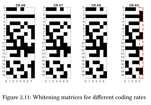
Whitening (Randomizing) is a technique that uses XORing bits with a pseudo-random sequence to remove the DC-bias from transmitted data. Unlike Manchester coding, it maintains the same data rate, but does not guarantee the removal of DC-bias, only a high probability of doing so.
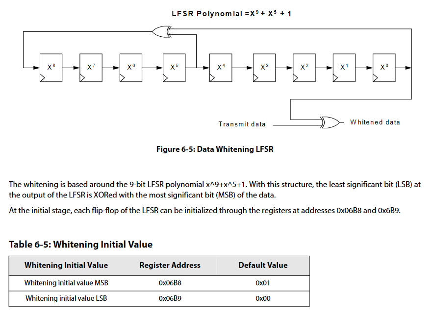
LoRa chip datasheet (Semtech. Data Sheet SX1276/77/78/79, Rev. 7, 2020) mentions that the whitening sequence in FSK mode is generated by a Linear Feedback Shift Register (LFSR). We guess that there also exists a LFSR generating the whitening sequence for LoRa mode. We apply Berlekamp-Massey algorithm on the whitening sequences of the two decoding orders to obtain the corresponding LFSR.
Important Note: The whitening is based around the 9-bit LFSR polynomial x^9+x^5+1. With this structure, the least significant bit (LSB) at the output of the LFSR is XORed with the most significant bit (MSB) of the data.
- Simple snippet
Multiprocessing and Multithreading
Multithreading and multiprocessing are techniques used to improve the performance of code by allowing multiple tasks to be executed simultaneously.
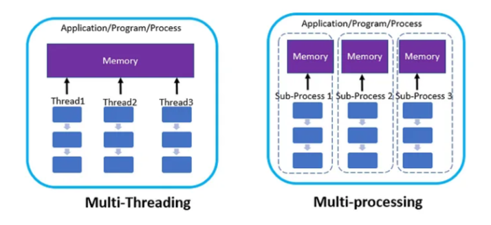
Multithreading is a technique where multiple threads of execution are created within a single process. Each thread runs independently, allowing multiple tasks to be performed concurrently. In a multithreaded program, each thread shares the same memory space and resources, but each thread has its own stack and set of registers. Multithreading is often used in programs that perform I/O or other blocking operations, where one thread can wait for I/O to complete while another thread performs computation.
Multiprocessing, on the other hand, is a technique where multiple processes are created, each with its own memory space and resources. Each process runs independently, allowing multiple tasks to be performed concurrently. Multiprocessing is often used in programs that perform CPU-intensive tasks, such as image or video processing, where multiple cores or processors can be utilized to improve performance.
The key difference between multithreading and multiprocessing is that multithreading allows multiple threads to execute within the same process, while multiprocessing allows multiple processes to execute concurrently.
Both techniques can improve code performance by leveraging the power of modern CPUs, which typically have multiple cores or processors. By dividing tasks among multiple threads or processes, the workload can be distributed across multiple cores or processors, resulting in faster execution times. However, the choice of whether to use multithreading or multiprocessing depends on the nature of the task being performed and the resources available. In general, multithreading is preferred for tasks that involve I/O or other blocking operations, while multiprocessing is preferred for tasks that are CPU-intensive.
Suppose we need to read and process a signal file that has a large data size. Reading and processing the signal would take a significant amount of time. To improve the performance, we can use multithreading for the signal readout sequence and multiprocessing for the signal processing sequence. Here is the code for the signal readout and processing, including fixed-point conversion:
Since reading the file is an I/O bound operation, let’s apply multithreading to the readout part now:
To implement multithreading for the readoutSignal function, we can split the input file into multiple parts and read each part in a separate thread. In this implementation, the num_threads parameter specifies the number of threads to use. The file_size variable is calculated using the os.path.getsize function, and the chunk_size is calculated based on the file size and the number of threads. The chunks variable is a list of file positions, each representing the start of a chunk.
We create a thread for each chunk using the threading.Thread constructor and pass the read_chunk function as the target. The args parameter is used to pass the start and end file positions to the function. We start each thread with the start() method. After starting all threads, we wait for them to complete using the join() method. Once all threads have completed, we concatenate all the results in the results list and return the final read input data as a single array.
Now, let’s apply multiprocessing to the signal processing part, specifically the fixed-point conversion, since file processing is a CPU-bound operation:
This code defines a function called multiprocessFixedtoFloat that takes in an input_data array as an argument. The goal of this function is to convert the fixed-point numbers in input_data to floating-point numbers using multiple processes to speed up the computation. The first line of the function uses the multiprocessing.cpu_count() function to get the number of available CPUs on the system, and then subtracts 1 to leave one CPU available for other tasks. This value is stored in the num_cpu variable. Each chunk is created by slicing the input_data array into a piece of length pool_length. The chunks are stored in the chunks list. The multiprocessing.Pool() function is then used to create a pool of worker processes, with the number of processes equal to num_cpu. The pool.map() function is used to apply the convertFixedPoint function to each chunk of input_data in parallel. The pool_results variable is assigned the result of the pool.map() function, which is a list of arrays of floating-point numbers. The pool.close() function is then called to close the pool of worker processes.
[References]
- Liando, Jansen & Jg, Amalinda & Tengourtius, Agustinus & Li, Mo. (2019). Known and Unknown Facts of LoRa: Experiences from a Large-scale Measurement Study. ACM Transactions on Sensor Networks. 15. 1-35. 10.1145/3293534.
- Tapparel Joachim, Complete Reverse Engineering of LoRa PHY: https://www.epfl.ch/labs/tcl/wp-content/uploads/2020/02/Reverse_Eng_Report.pdf
- https://lora.readthedocs.io/en/latest/
- Modulation, 2015. LoRa Modulation Basics, Rev.2., https://www.semtech.com/uploards/documents/an1200.22.pdf
- Kosta Dakic et al, LoRa Signal Demodulation Using Deep Learning, a Time-Domain Approach
- https://www.rfwireless-world.com/Tutorials/LoRaWAN-MAC-layer-inside.html
- Zhenqiang Xu, Pengjin Xie, Shuai Tong, and Jiliang Wang. 2022. From Demodulation to Decoding: Towards Complete LoRa PHY Understanding and Implementation. ACM Trans. Sen. Netw. Just Accepted (July 2022). https://doi.org/10.1145/3546869
- Ghanaatian, R., Afisiadis, O., Cotting, M., & Burg, A. (2019). Lora Digital Receiver Analysis and Implementation. ICASSP 2019 - 2019 IEEE International Conference on Acoustics, Speech and Signal Processing (ICASSP). doi:10.1109/icassp.2019.8683504
- https://www.youtube.com/watch?v=MsMkiTcc_w0


