1) Objectives
The key objectives of the project are the following: become accustomed to the Modelsim, Verilog Hardware Language, and the concept of digital system design. Based on this knowledge, we should apply these concepts to design the cashier machine with some given constraints, such as clock frequency, clock delay for each module, asserted cycles, number of the multiplier, etc.
2) Design Descriptions
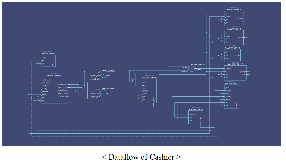
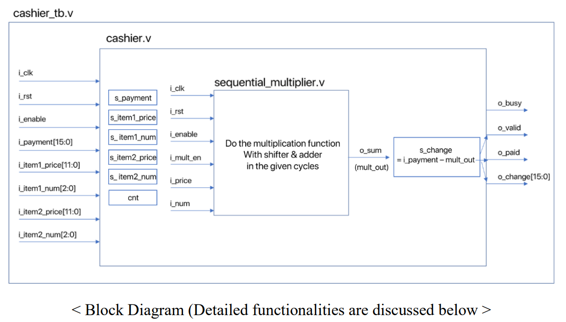
The code ‘cashier.v’ plays the main role of the cashier functionality. The code proceeds the operation with respect to the input payment, items’ prices, and numbers with constraints of the size of bits. After receiving the input values, the code does some calculations and shows the state of the cashier, for instance, busy/idle state, valid, paid or not, and if paid, shows the change. In this procedure, the various registers and modules are declared.
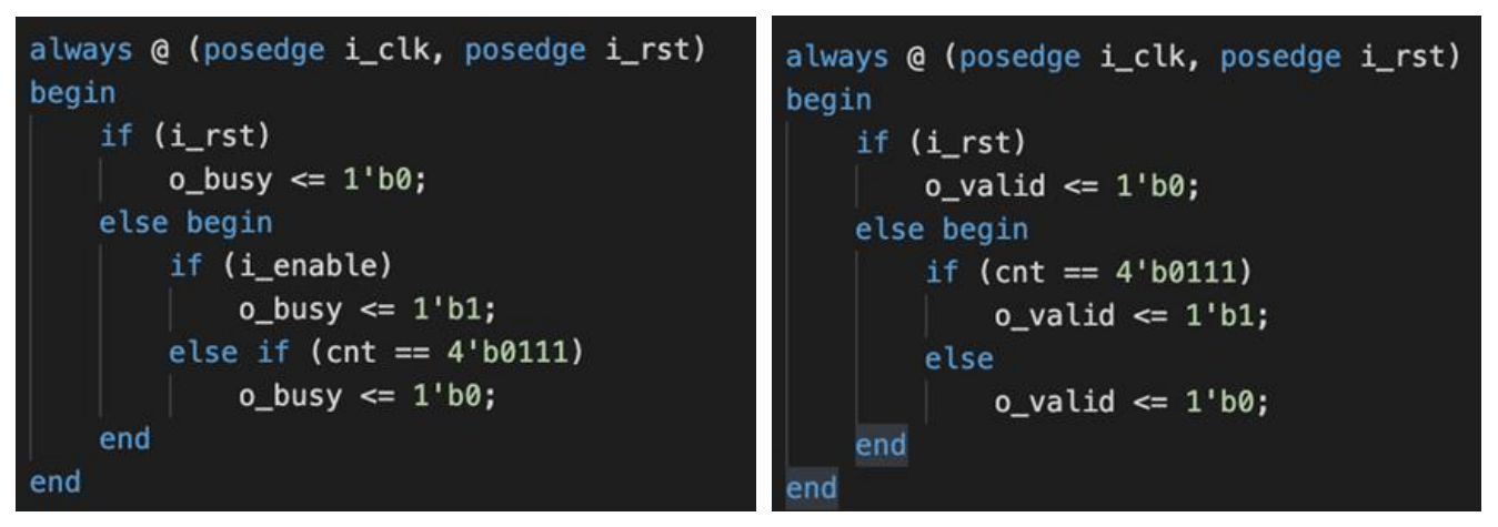
Some considerations should be considered, such as clock delay for each module and asserted cycles of the values. We implemented these functionalities, i.e., the clock cycle counter, with simple if-else statements. For instance, to satisfy the condition for o_valid and o_busy, we can implement the if-else statements as follows:
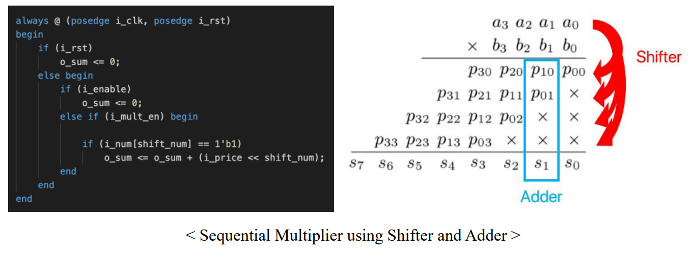
Since the usage of the multipliers is restricted, we tried to use the separated sequential multiplier module code ‘sequential_multiplier.v’ to do the multiplication operation. The basic idea of multiplication is shifting and adding, as we do the arithmetic calculation.
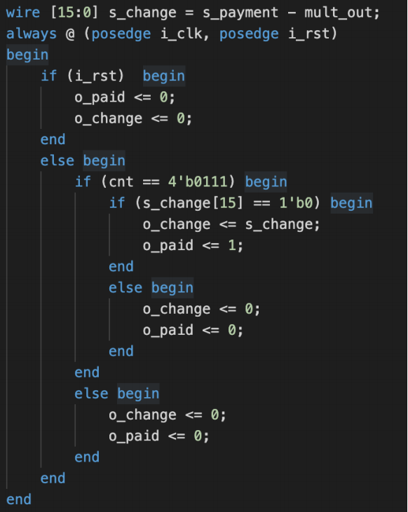
The above considerations were the detailed one, which should be repeatably debugged by obtaining the waveform. The main functionality of the cashier is to subtract the required value to buy from the inserted payment. If the change has a positive value, we can regard as the payment is valid. If the change has a negative value, vice versa. We implemented a simple if-else statement to operate these functionalities as follows:
3) Experimental Results
If we insert a 10k bill and choose 2 of 3.5k item1 and 2 of 1k item2, the payment is done, thus prints 0_paid =1’b1, and the o_change should be 10k-3.5k2-1k2=1k, which shows the accurate result. This result shows an identical result as the guideline’s example result.
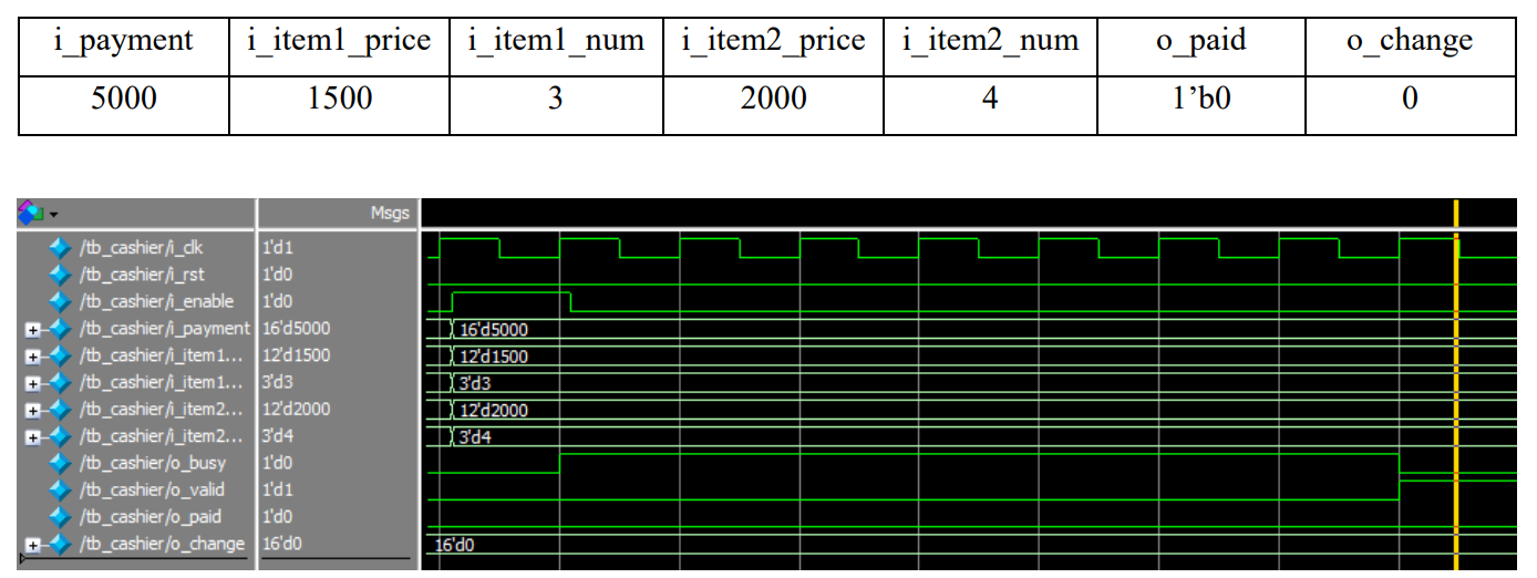
If we insert a 5k bill and choose 3 of 2k item1 and 4 of 2k item2, the payment is not done, thus prints 0_paid =1’b0 since the payment is not sufficient. The o_change value should be 0 since the o_paid value is equal to 1’b0. Although the payment is not done, o_valid should have the value 1’b1 since the output signals are valid. This result shows an identical result as the guideline’s example result.
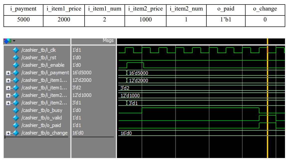
If we insert a 5k bill and choose 2 of 2k item1 and 1 of 1k item2, the payment is done, thus prints 0_paid =1’b1, and the o_change should be 5k-2k2-1k1=0, which shows the accurate result. The common feature between this result and the above result is that both of these cases have 0 charge. The difference is that the o_paid value is 1 because the payment is successful.
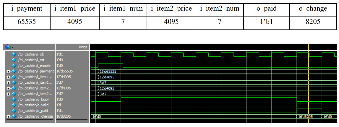
If we insert 65535 cents and choose 7 of 4095 cents item1 and 7 of 4095 item2, which are the maximum values that could be expressed in a given size of bits (16bits, 12bits, 3 bits, respectively), the payment is done, thus prints 0_paid =1’b1. The o_change should be 65535-409572 = 8205, which shows the accurate result.
From the above results, we can conclude that our Verilog-code-based cashier is well-designed. Revisiting our objectives, we can understand the concepts of the digital system design and apply these concepts to the design of a cashier machine with the project.
